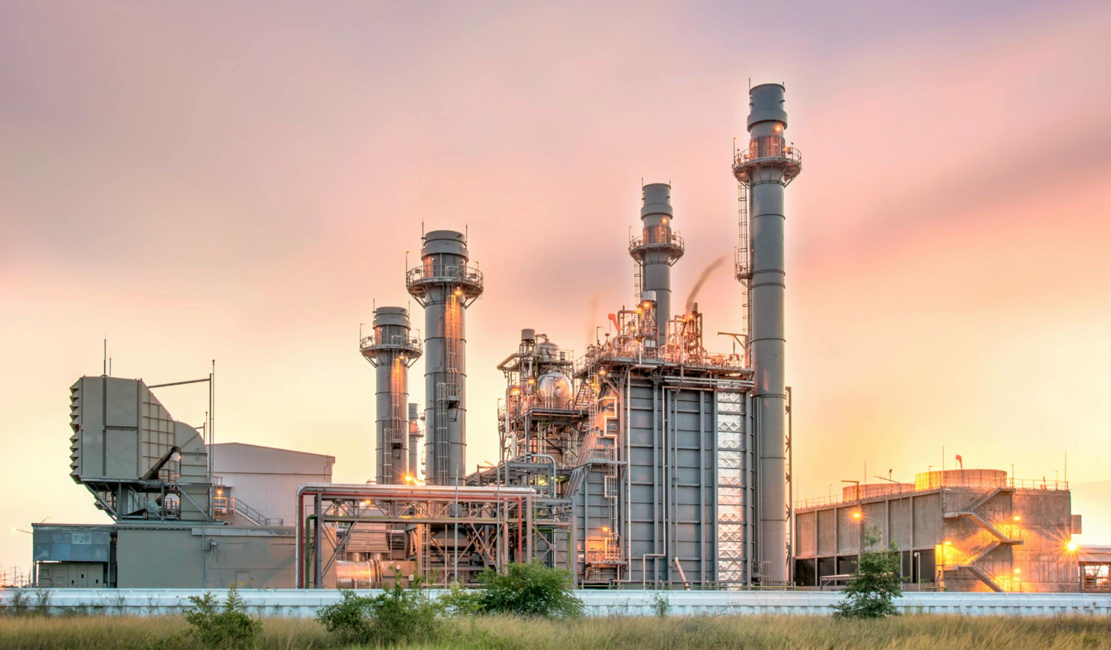
Cogeneration

Customer Success Story

Cogeneration systems generate electricity using a natural gas fired turbine. Rather than have the hot exhaust gases released directly, the hot exhaust is routed to a secondary process in order to create steam.

The steam is then used as part of a manufacturing process or introduced to a steam turbine for additional electricity generation. Because of the dual use from a single fuel source, cogeneration systems are extremely efficient.

Compared to traditional fossil fuel or nuclear power generation, cogeneration systems are much smaller in terms of output capacity. However, they don’t require the environmental permits that other fuel types do, and can be a relatively fast way to add electrical capacity. Cogeneration systems are often used as back-up or secondary sources to supplement the electrical grid during periods of high demand. Because of this, their operation is often very cyclic in nature.

Location

West Coast, USA

Operating Temperature

1800°F (980°C)

Application

Power Generation

Project

Cogeneration Ducts

NUTEC Products

MaxBlock 2300 Modules, MaxWool 2300 Blankets

Anchoring Method

Prewelded Stud-Tite Studs

Installation Technique

Unidirectional Construction with Single Folded Batten Strips

11/08/2023
3 Minutos
Power Generation – Cogeneration

The Challenge

Since cogeneration uses a natural gas fired turbine as the initial step to generate electricity, internal air velocities inside the system are very high. These velocities are typically above the velocity ratings for high-temperature fiber insulation systems. The most common type of refractory system employed is a stainless steel hot face cladding that will withstand the internal wind velocity, backed up by high-temperature ceramic or soluble fiber blankets.

Downstream from the gas turbine, additional heat is often added to the air stream to increase the temperature of the exhaust gas which is being sent to the steam turbine. In these duct sections, the temperatures are often too high for stainless steel cladding, and a refractory system that can withstand the application temperature and internal velocity of the ducting is required.

Critical requirements that owners/operators of cogeneration systems have for fiber-based lining systems are:

Thermal Shock Resistance

• Because of the cyclic nature of their operation, cogeneration plants require an insulation system that is immune to thermal shock. Many traditional refractories (bricks or castables) are not suitable for this application, given the frequent thermal cycling and resultant potential thermal shock for the refractory system.

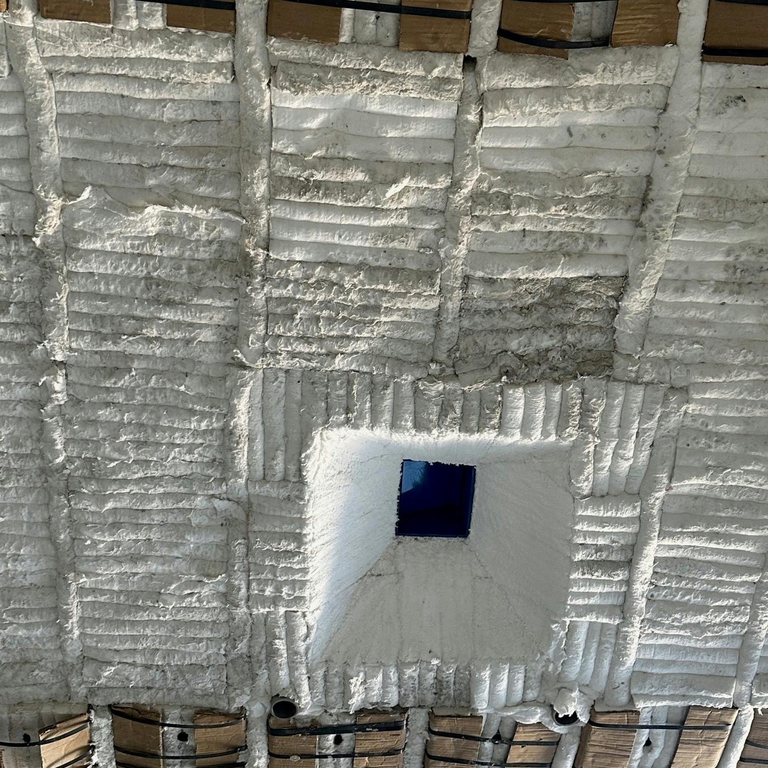
Internal Air Velocity Resistance

• Internal air velocities can be very high, especially once additional heat is introduced into the air stream. The refractory system must be able to withstand the operating velocities without degrading over time.
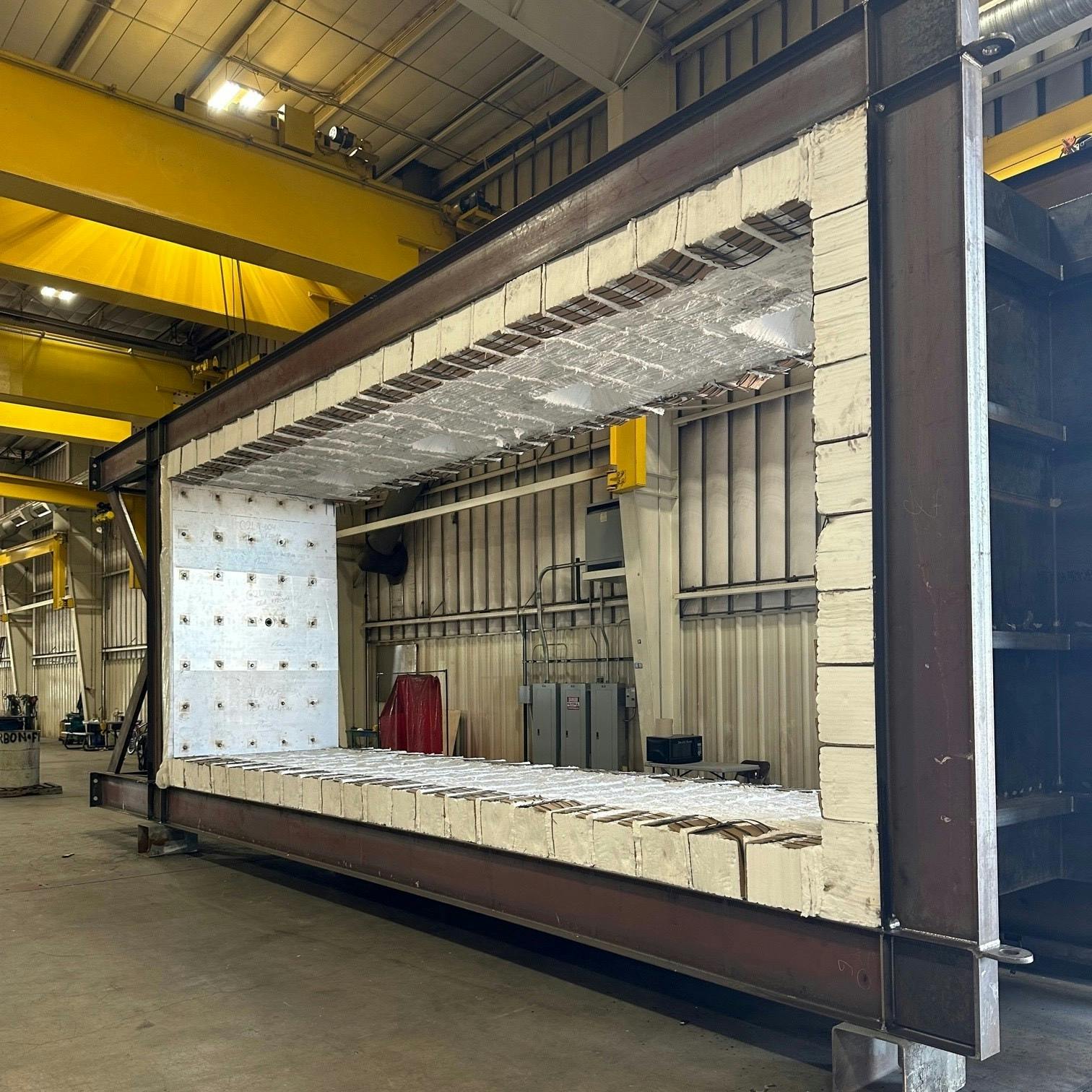
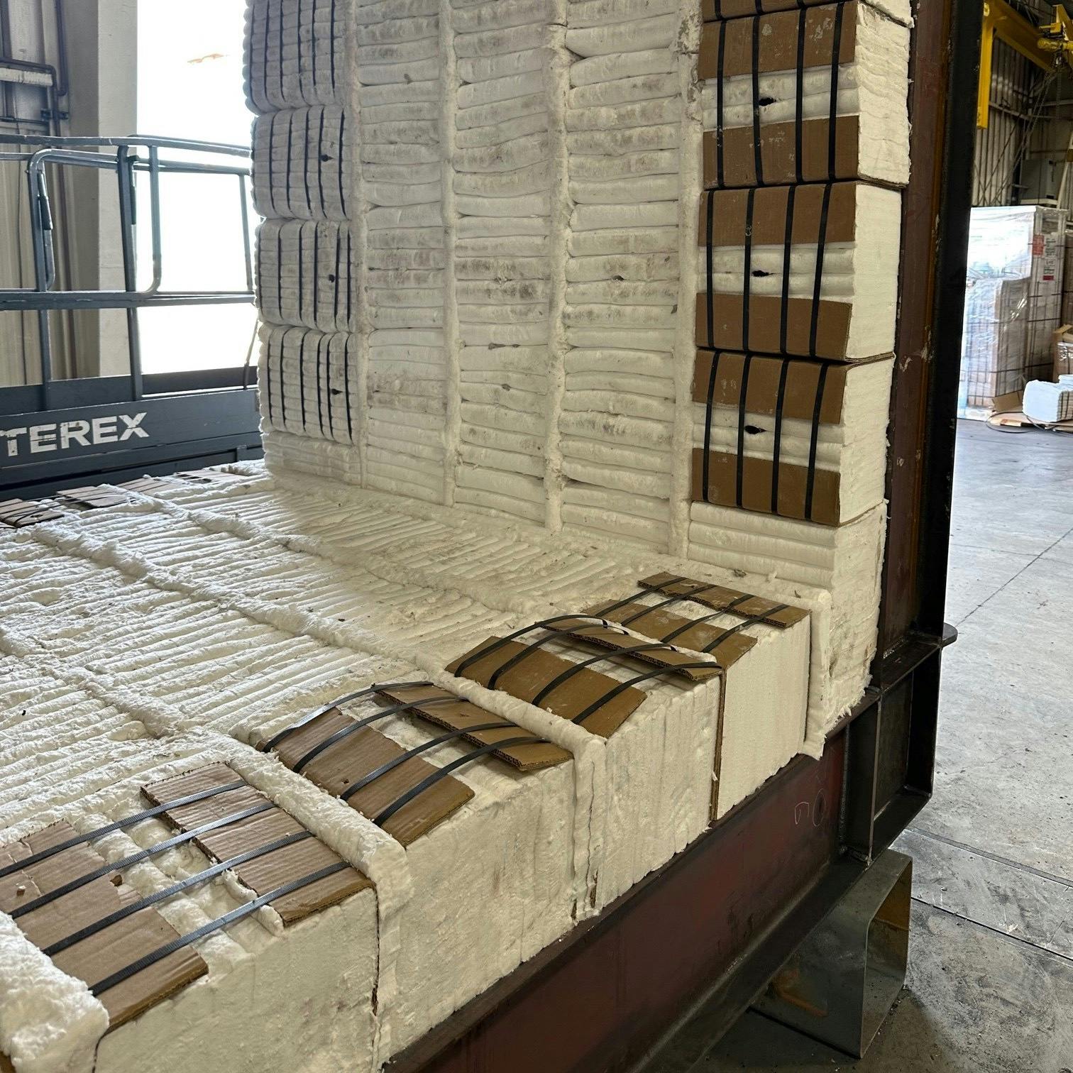
System Weight

• Cogeneration ducting is most often produced and insulated at the location of a steel fabricator and then shipped to the end user in completed sections. Using a fiber-based system provides the lightest weight option for shop installation and subsequent erection in the field.

Stud- The Modules are easily shop installed using an engineered stud layout to accommodate easy field erection.

Fig. 1 Stud- The Modules are easily shop installed using an engineered stud layout to accommodate easy field erection.

Solutions

For this application, MaxBlock 2300 Modules were selected. These modules feature a folded hot face construction that is very durable in high temperature and elevated velocity applications. Folded batten strips were installed between each module row. MaxBlock Modules are completely immune to thermal shock and can withstand the frequent thermal cycling of the application. To ensure maximum integrity when it came to securing the modules in place, a prewelded anchoring system was provided. The Stud-Tite anchoring system allows for full inspection of the stud weld quality prior to attaching the module to the steel casing plate using a Stud-Tite Stud. A prewelded stud system also ensures that the appropriate number of modules are installed per row and at the specified module-to-module spacing.

Results and Benefits

The MaxBlock Module system that NUTEC provided for this application met all the demanding customer requirements of air velocity and thermal shock resistance, along with minimal weight for shop installation and shipment.

For section perimeters, module banding and endcaps are typically left in place for protection during shipment.

Fig. 2 For section perimeters, module banding and endcaps are typically left in place for protection during shipment.

Specially designed module sizes can be provided to design around sight ports, burner assemblies and other types of lining penetrations.

Fig. 3 Specially designed module sizes can be provided to design around sight ports, burner assemblies and other types of lining penetrations.

The Takeaway

NUTEC’s experienced application engineers evaluated the operating conditions and offered an engineered solution complete with detailed installation drawings that were provided at no additional charge. NUTEC’s broad product offerings afforded many selection options designed to supply the end user with a high-quality insulation system that will provide them years of service.